|
Use of Electronic Test Equipment |
|
Introduction |
| |
********
The electronic data in this section has largely been supplied by CDI Electronics, a
division of Rapair, Inc. CDI Electronics has been the leader in outboard marine
ignition technology since 1983, and their products are marketed under the name of
"Quick Strike Ignitions". Outboardparts.com features CDI Electronic
Products throughout our site. This information is supplied as a service guide only and
Outboardparts.com is not liable for any misunderstandings, errors or omissions
regarding this information. The information has been obtained from actual unit analysis,
parts manuals, and other sources. ******** |
| |
| The purpose of this brochure is to give the marine technician a general overview or
the types of test equipment and their use. The most common, easy to use, test
equipment will be covered. |
| Due to the rapid development of computerized EFI (Electronic Fuel Injection) and ECU
ignition systems, more complicated and expensive test equipment will be developed for the
marine industry, just as it has been developed for the automotive industry. Some newer
equipment will include the use of scope meters (such as the Fluke 98), ECU and EFI
testers, digital analyzers, and computer interface testers. Hopefully, the newer test
equipment will be user friendly and many troubleshooting problems will be diagnosed with
less complicated equipment. |
| |
| The test procedures at the end of this brochure are intended to give the technician a
better understanding of the most common failures and allow testing with minimal equipment. |
| |
Test Equipment and Measurements |
|
| I. VOM (Volt-Ohm-Meter) Multimeter |
A. Analog meter - The analog VOM is a dial/needle
movement with multiple switch settings and ranges on each setting. This meter usually
requires "calibrating" of the scale before use. |
They normally consume batteries at a fast
rate. |
| |
| B. Digital meter - The digital VOM uses a digital display to indicate
the readings. Of the following types, the manual and autoranging are the most popular |
| |
| 1. Manual range setting - The
measurement range is selected by a switch, i.e. 20 ohm, 200 ohm, 2k ohm,
200k ohm and 20M ohm. The symbol for ohms is W. |
|
|
| 2. Autoranging - A true
autoranging meter will automatically select the correct range for the measurement being
taken, i.e., you can measure 20 ohms and 2k ohms without changing anything on the
meter. The TYPE of measurement still has to be manually selected, i.e., AC Volts, DC
Volts, Ohms, AC Amps and DC Amps. |
|
| 3. Manual / Autoranging - Some
meters have both manual and automatic settings, i.e., the Fluke 88,
Fluke 29, etc. |
|
| 4. Ranges - As a reminder, when
referring to electronics, the k is 1000, i.e., 1k ohm is 1000 ohms and 20k ohms is 20,000
ohms. The M is 1,000,000 i.e., 2M ohm is 2,000,000 ohms. |
|
| |
| II. Peak Reading Voltage Measurement |
| |
| A. DVA (Peak
Reading) Voltmeters - Specialty meters for measuring average DC voltages and AC
voltage spikes on ignition systems. Some of the more common meters include the Stevens
CD-77, Merc-o-tronic and ESI meters with DVA ranges. |
|
| B. Multi-use
Voltmeters with DVA Adapters - Analog or digital VOM (volt, ohm meters) using a
plug-in DVA adapter to measure DVA voltages. Accuracy varies quite a bit between
manufacturers and types of meters when taking DVA readings. The CDI/Rapair 511-9773 peak
adapter is highly recommended for use with all Fluke meters. |
|
|
| III. RPM (Tachometer) Measurements |
| |
| A. Inductive Tach
Measurements |
| This type measurement is made by clamping an inductive pickup
probe on one of the spark plug wires. Very few of the inductive systems will work well on
two cycle CD ignitions due to the RF and microwave noise being generated. The Fluke 88
Multimeter used with the CDI/Rapair 511-9788B two cycle adapter, is highly
recommended. The Merc-o-Tronic Inductive Tach and the CDI/Rapair Tach
Adapter (P/N 511-9785) are some of the units recommended for both two and four cycle
service. Inductive tachometers can be a real time-saver when trying to find a high
speed miss by comparing the readings on all cylinders, i.e., if one or two cylinders shows
a big difference in comparison to the other cylinders. The use of inductive tachometers is
recommended for detection of double firing cylinders. If one cylinder shows twice the RPM
of the other cylinders, it is probably double firing. |
|
|
| |
| B. Reflective Tach
Measurements - These are optical tachometers, that use a piece of reflective tape
on the flywheel or pulley. |
| |
| C. Contact Tachometer
- NOT RECOMMENDED FOR OUTBOARD USE. |
| Uses a center hub rotator and counts the RPM.. |
|
| |
| D. Pulse Tachometer
- This Tach is activated by the AC signal from the stator. The RPM signal is related
to the number of pulses received from the stator. |
|
| |
| IV. Temperature Measurements |
| |
| A. Thermocouple / Meter
System |
| This is probably one of the most useful systems. The Fluke 51 and 52
temperature meters, or the accessory temperature attachments for the Fluke meters, are
capable of measuring exhaust gas temperature, water temperature, head and block
temperature. Various probes are available for different types of measurement with the bead
probe being one of the most useful. The bead probe can be positioned on the block with the
use of duct tape. |
|
| |
| B. Infrared
Temperature Probes |
| They can be used to measure temperature at various points on
the engine or water temperature without contact. However, some running engines generate
too much electronic static and will interfere with the infrared sensor readings.
Holding the temperature probe too close may cause the ignition noise to ruin the unit. |
|
| |
| C. Temperature Sticks,
Paint or Labels |
| These can be used for quick measurementof over heating
conditions. |
|
|
| |
| V. Pulse Measurements / Frequency Measurements |
| This is a good method to check electronic fuel injection systems (EFI). A
measurement of the injector pulses at a set RPM can determine if the injection system is
performing properly. At the current time there are few recorded measurements on the
various EFI systems. The Fluke 88 meter is one of the meters designed to measure EFI pulse
rates. |
|
| |
| VI. Resistance Measurements |
| This is one of the first and easiest measurements that needs to be
taken on an ignition system. The charts in the back of this brochure are furnished
as a guide. Be aware that temperature can make a slight difference in the readings.
The higher the temperature - the higher the resistance reading is going to be. One final
note, a stator or trigger can test fine with an ohmmeter and still be bad.
|
|
| |
| VII. Current Measurements |
| |
| A. Direct Volt Amps
(DVA) |
| One of the most important measurements to be taken on
ignition systems are voltage measurements using a DVA meter, or peak reading (DVA) adapter
with a good VOM. The Fluke *a kit is highly recommended by out Technical Service
Department. The charts in the back of this brochure give the readings for a majority of
the engines. On an engine with a split ignition, if only one side fires, compare the
readings between the sides. Typically, the DVA readings for Yamaha and Suzuki will be
close to that of Mercury. A simple test on rectifier/regulators (except
OMC rectifier/regulators without cooling fins on the bottom) can sometimes be a
time-saver. With the engine running at approximately 1200-1500 RPM. DVA test from each
yellow wire to engine ground. The readings should be within 11/2 volts of each other,
i.e., if one wire reads 20 volts - the other has to read between 18 1/2 and 21 1/2
volts. If one wire reads low, mark the stator and rectifier wire with the low
reading, shut the engine down and swap stator wires. Crank the engine up and repeat the
test. Whichever part with the striped wire that has the low reading is bad. Repeat the
test for yellow wires to the red wire going to the battery / solenoid. |
|
| |
| B. DC Voltage
|
| Most battery CD ignition modules are sensitive to low battery
voltage and battery reversal. During cranking, a DC voltage level at the pack of less than
9 !/2 Volts is unacceptable and indicates a problem in the harness, keyswitch, starter or
battery. WOT voltages above 16 volts will blow most battery ignitions. Problem is likely
to be either the battery or cables. |
|
|
| |
| VIII. Current Measurements |
| |
| This is a good way to check the regulator/rectifier battery charging
operation in the charging system. The 10 amp charging system can be checked with a good
VOM that has up to 10 amp capability (Fluke 29,73,88, etc.). The red wire is disconnected
from the rectifier, the one meter probe is placed on the connection, and the other is
placed on the red wire. |
|
| |
| Warning! Make sure you do not exceed 10 amps or touch
ground with one probe. This could damage the meter. The 35 amp
charging system requires an inductive pick up or a high current amp adapter, such as
CD/Rapair's 511-9772 (1-400 amp). Remember, on outboard charging systems at idle speed the
current is @ 1/5 of the current rated. |
|
| |
| IX. Battery CD Tester |
| |
| This is used to test battery CD modules on the engine by replacing the
points or triggering device electronically. The CDI 511-9701 Battery CD Tester is highly
recommended due to its ability to fire the ignition systems up to 3000 RPM without the
engine running. It can be used to test the CD module, distributor cap, ignition coil and
plug wires. Additionally, the tester can be used to test Mercury EFI injectors. |
|
| |
| X. EFI Tester |
| |
| Electronic fuel injection testers are available for use with the specific
type of EFI system it was designed for. Use of these testers are not covered in this
brochure. |
|
| |
| XI. Trigger Tester |
| |
| A break through by CDI/RAPAIR (511-9710) allows you to test
most Mercury, Mariner, Force, Chrysler triggers and OMC 's Quick Start timer bases on the
engine. The unit can be used to test points, preamp triggers, Mercury battery CD triggers,
hall effect triggers, alternator driven ignition triggers, and can be used to check
injection pulse from Mercury EFI modules. |
|
| |
Tricks to Testing with Minimal Test Equipment |
|
All Engines |
|
| Intermittent Firing: This problem can be very hard to isolate. A good
inductive tachometer (fluke 88 is recommended) can be used to compare RPM on all cylinders
up through wide open throttle. A big difference on one or two cylinders indicates a
problem. |
|
| Two or more cylinders misfiring: It is recommended that both power
packs be replaced, unless the problem is a bad trigger. |
|
| Engine continuously blows power packs: When an engine starts blowing
power packs repeatedly, especially on the same cylinders, replace the ignition coils on
those cylinders. The inductive kickback from a bad coil can destroy the packs, even if the
coils check good with all known tests. A stator that test good can also be sending spike
voltages to the packs causing them to fail repeatedly. |
|
| Visually check the stator, trigger and flywheel: Cracks, burned marks
and bubbling on the stator or trigger indicate a severe problem. If the stator shows
bubbling around the battery charge windings, more than likely you will have to replace the
rectifier/regulator in addition to the stator. Signs of rubbing on the flywheel usually
indicate a bad upper or lower bearing. Check both the outer trigger magnets for signs of
cracking and to be sure that they are not loose. |
| |
OMC |
| |
| Open type timer bases: When all cylinders fire with the spark plugs
out, but one or more cylinders quit when the spark plugs are reinstalled, regapping the
timer base may solve this problem. Please refer to the troubleshooting guide for
OMC power packs and CD's item #8. |
| |
| Quick Start timer bases: These timer bases cannot be checked
like the other timer bases. Please refer to the troubleshooting guide for
OMC power packs and CD,s item #5. |
| |
| Engines with SLOW features: If the complaint is that the engine will
not slow down after a few minutes and starts shaking real bad, (but the engine is NOT
overheated) try replacing the temperature switch (the one with the white/black and tan
wires coming out). Check routing of tan wires. Relocate as far from the spark plug wires
as possible. Check blocking diode in engine harness. |
| |
Mercury 6 Cylinder with ADI ignition |
| |
| No fire on the 1,3,5 or 2,4,6: Swap red and red/white wires, also
blue with blue/white wires. If the problem moves to the other set of cylinders, the stator
is at fault. Disconnect rectifier and retest. If the engine fires normally, replace the
rectifier. If no change, we recommend replacement of the stator. If you replace the stator
and the problem remains try another flywheel, if possible. |
| |
| No fire on one cylinder: Since this condition can be caused by the
opposite switch box (pack), disconnect the white/black jumper between the packs and
retest. If the dead cylinder starts firing, replace the pack that was firing all three
cylinders. As a verification, swap the trigger and spark plug wire to the cylinder closest
to the dead cylinder, (i.e., if #1 is dead, swap the brown trigger wire with the white
one). If the problem moves to #3, replace the opposite power pack (switch box). If #1 is
still dead, swap the green and green/white coil wires. If the problem moves to #3, replace
the power pack (switch box). Please remember to put the trigger wires in the correct order
after you finish. |
| |
| Always check the bias circuit: Disconnect the jumper between the
packs on the white/black posts. Check the resistance from the white/black posts on each
pack to engine ground. Standard packs will read from 13-15,000 ohms. Racing boxes will
read approximately 9,600 ohms. MAKE SURE THAT THE BIAS READING IS THE SAME ON BOTH
PACKS!!! If the bias is out of specification on one pack you must replace both packs to
prevent future damage. This circuit effects ignition timing and could cause a powerhead
failure. |
| For more detailed information, please refer to the troubleshooting guides on the other
pages. |
| |
Troubleshooting OMC Battery CD Ignitions |
|
| Recommended Tools: |
| For DVA: |
Fluke Multimeter with CDI #511-9773 Peak Adapter, (or CD-77) and CDI #511-9770 |
|
CDI #511-9701 Battery CD Tester |
|
CDI #511-9766 Spark Gap Tester |
|
Jumper Wires |
|
A Reliable Volt/Ohm Meter (if the CD-&& is used for the DVA |
| CAUTION; DO NOT USE A MAINTENANCE FREE BATTERY WITH THESE TYPES OF
IGNITIONS AS THEY TEND TO OVERCHARGE AND BLOW THE PACKS.> Typically 17 Volts +. |
| |
| Note: A large portion of the problems with the battery CD units are caused
by low battery voltage or bad ground connections or high battery voltage. Low Voltage
symptoms are weak erratic firing of cylinders. Misfiring after a few minutes of running
can be caused by excessive (Over 15.5 Volts DC) voltage at the pack - See #2 below. |
| |
| 1) Check all battery and ground connections. |
| |
| 2) Check the Voltage on the red (or purple) wire at the CD
unit. |
| If the voltage is less than 9 1/2 volts during the cranking
there is a problem in the battery circuit. These units require at least 9 1/2 volts to
fire properly. Connect a jumper wire directly from the battery (+) terminal to the red (or
purple) wire. Retest. ATTENTION: In order to kill the engine if it cranks, the jumper wire
must be disconnected and/or choke the engine. If the engine still fails to crank, recheck
voltage as above. If low, replace the battery and retry. WARNING: Check
he voltage on the red (or purple) wire at the CD unit through the RPM range. At no time
should the voltage exceed 15.5 Volts DC. |
|
| |
| 3) Disconnect points and/or sensor wire and connect a battery
tester. |
| Hook up the Battery CD Tester according to the operators manual and align
rotor with spark plug wire. Connect a spark gap to all spark plug wires and turn the
ignition switch on. If the CD unit fires only to one spark plug wire, check the points,
sensor, anti-reverse spring and wires for breaks and shorts. If ANY other spark plug wire
fires besides the one the rotor is aligned with, the distributor cap and rotor should be
replaced. The Battery CD tester will fire the system to approximately 3000 RPM. If the
Battery CD tester (511-9701) is not used, strike points wire against engine ground. For
the sensor, strike the two wires together. The CD unit should fire every time. If the CD
unit fails to fire, it is usually bad. |
|
| |
| 4) Points type ignition. |
| Disconnect points wire and check voltage on the points wire. You should
read close to battery voltage with the key switch on. No voltage means a bad pack. If OK,
reconnect the points wire. Using the piercing probes (511-9770) connect the DC volt meter
to the points wire. Turn the switch on and slowly rotate the flywheel. You should see the
voltage fluctuate up and down. |
|
| |
| 5) Check the ignition coil. |
| An open, cracked or poorly grounded coil can burn out a battery CD unit. |
|
| |
| 6) Check the DVA voltage on the primary input wire to the coil. |
| Reading should be approximately 200 volts or more. |
|
| |
| 7) Simplified bench test: |
 |
| |
Troubleshooting OMC
Power Packs
and CD's |
| |
| Recommended Tools: |
| For DVA: |
Fluke Multimeter with CDI #511-9773 Peak Adapter, (or CDI #511-9770 Piercing
Probes |
|
CDI #5119-710 Trigger tester (for use with '88-'96 V8, V8 Quick Start timer
Bases |
|
CDI #511-9766 Spark Gap Tester |
|
CDI #553-2697, 553-2698, 553-2699 Pin Removal and Insertion Tools |
|
CDI #553-9702 Gap Gauge |
|
Jumper Wire |
| Note: If CD-77 is used for DVA, you will need a good
volt/ohm meter. |
| |
| NOTICE: Initial DVA readings should be taken with
everything hooked up. |
| |
| 1) Check the flywheel for cracked and lose magnets. |
|
| 2) Disconnect the kill wire(s) from the pack and retest. |
| Connect a DC voltmeter between the kill wires and engine
ground. Turn the ignition switch on and off several times. If at any time, you se DC
voltage appearing on the meter, there is a problem in the battery harness or the ignition
switch. NOTE: At no time should you see battery voltage on any kill wires. |
|
| |
| 3) Visually inspect stator for cracks or leaks: |
| If found, replace the stator, Burnt marks of discolored areas on the
battery charge windings indicates a possible problem with the rectifier. |
|
| |
| 4) Unit will not fire: |
| Disconnect the kill wire AT THE PACK. Check for bare or broken
wires on the unit, stator and timer base. Measure DVA voltage of the stator with
everything connected. Readings should be approximately 150 volts or more. On standard CD
types, check DVA voltage on the timer base white wire. Voltage should be approximately 150
volts or more (Quick Start units usually have the white wire tied to ground inside the
pack). If the reading is good on the stator but low on the white wire, the timer base is
usually bad. Disconnect the rectifier. If the engine fires, replace the rectifier. |
|
| |
| 5) '88-'98 V6-V8 and 93-98 3 cylinder Quick Start timer
bases: |
| Disconnect the timer base. Using the Fluke meter, set to ohms
scale, and one of the piercing probes, connect the red lead from the meter to the white
wire in the Amphenol connector from the timer base. Use the black lead from the meter and
check to all of the pastel colored wires in both connectors from the timer base. All of
the readings should be fairly even, normally between 1 and 2 meg ohms measured with a
Fluke meter. With the red lead still connected to the white wire, connect the black meter
lead to the black/white wire in the opposite connector from the timer base. You should
read approximately 220 ohms. If one or more cylinders are out of line, (I.E. all the rest
are reading 1.2 -1.8 meg ohms and one reads 0.898 or 2.2 meg ohms) the timer base is
usually bad. |
|
| |
| 6) '92-'96 Looper units with optical triggers: |
| DVA check the stator. Each set of brown wires should read at least 150V
(950-1050 ohms) and 12 volts between the two orange wires from the power coil (50 ohms on
the gray sleeved stator and 97 ohms on the black sleeved stator). Note: These units
require special spark plugs and the GRAY spark plug wires. If the pack only fires when you
remove the plug connector containing the kill wires, use a jumper wire to connect the kill
wires in the pack. If the pack still fires, there is a problem in the harness, safety
circuit or ignition switch. A no fire situation with the jumper in place indicates a bad
pack. |
|
| |
| 7) '89-'95 4 Cylinder Looper units: |
| If the engine misses on one cylinder with the white/black temperature
wire hooked up and does not with it unhooked, this is usually the timer base causing the
problem. |
|
| |
| 8) For PP2, 3, and 4 units: |
| If one or more cylinders will not fire with the spark plug installed],
check the timer base resistance between sensor leads: PP2, from
white/black to black/white; PP3 from black/white to all all whit/blacks; PP4
1-3 and 2-4, readings should be 10-20 ohms for all sensor coils. (some of the
older units with the metal cased CD's read 8-14 ohms). Regapping may solve the problem.
CDI Gap Gauge 553-9702 is recommended for PP3 and PP4. To regap, remove the epoxy covering
and loosen the small nuts on the center bolts going thru the heat shield. Loosen the
anchor screws holding down the sensors. Slide the sensor in toward the crankshaft until it
touches the gap gauge. (553-9702) or the metal stop at the bottom of the sensor. Paint the
face of the sensor or the trigger magnet on the flywheel, with a contact detector, and
reinstall the flywheel. Crank the engine over several times and remove the flywheel,
checking to see if the trigger magnet is striking the sensor face. |
|
| |
| 9) Engine will not kill: |
| Remove the black/yellow kill wire from the rubber connector to see if the
pin is broken. Check the kill circuit in the pack by using a jumper wire connected to the
black/yellow wire coming out of the pack and shorting it to ground. If this kills the
engine, the kill circuit in the harness or the boat is bad, or the ignition switch is bad. |
|
| |
| 10) Coils fire with spark plugs out but not in: |
| Check for dragging starter or low battery causing slow cranking speed.
DVA test the timer base. |
|
| |
| 11) Engine runs rough on one bank (4, 6 and 8 cylinder engines
with CD ignitions): |
| DVA check stator voltage to both sides. The readings should be fairly
equal. If it exceeds 400 volts, replace the pack on the bank. If unequal, swap banks with
the stator leads and see if the problem moves with the stator leads. If it does, replace
the stator. Disconnect one of the black/yellow kill wires, AT THE PACK. If the problem
goes away, replace the pack that was running smooth as is probably has a bad blocking
diode. |
|
| |
| 12) Intermittent firing on one or more cylinders: |
| Can be caused by low voltage from the stator of a bad timer base. DVA
test stator and timer base. Disconnect the rectifier and retest. If the problem
disappears, replace the rectifier. If it doesn't replace the pack |
|
| |
| 13) Check for broken wires and terminals; |
| Especially check inside the rubber Amphenol plug-in
connectors. We recommend that you remove the pins from the connectors and visually inspect
them. |
|
| |
Troubleshooting Mercury Battery CD
Ignitions |
| |
| Recommended Tools: |
| For DVA: |
Fluke Multimeter with CDI #511-9773 Peak Adapter, (or CD-77) |
|
CDI #511-9701 Battery CD Tester |
|
CDI #511-9710 Trigger Tester |
|
CDI #511-9766 Spark Gap Tester |
|
Jumper Wires |
|
A Reliable Volt/Ohm Meter (it the CD-77 is used for the DVA) |
| CAUTION; DO NOT USE A MAINTENANCE FREE BATTERY WITH THESE TYPES OF
IGNITIONS AS THEY TEND TO OVERCHARGE AND BLOW THE PACKS. Typically 17 Volts +. |
| |
| Note: A large portion of the problems with the battery CD
units are caused by low battery voltage or bad ground connections or high battery
voltage. Low Voltage symptoms are weak erratic firing of cylinders. Misfiring after
a few minutes of running can be caused by excessive (Over 15.5 Volts DC) voltage at the
pack. - WARNING : Check the voltage on the red (or purple) wire at the CD
unit through the RPM range. At no time should the voltage exceed 15.5 Volts DC. |
| |
WARNING!! BATTERY REVERSAL WILL USUALLY DESTROY
BATTERY CDs AND TRIGGERS. |
| |
| 1) Check all battery and ground connections. |
|
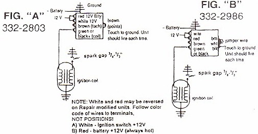
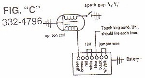
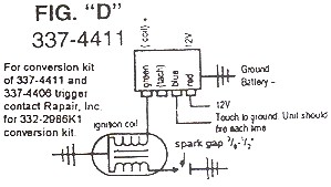
| 2) Dead or no fire until you release the key switch: |
| Disconnect the mercury switch and reset, if the engine
fires, replace the mercury switch. Check the voltage on the red and white ignition wires
at the CD unit. If the voltage is less than 9 1/2 volts during cranking there is a problem
in the battery s or the ignition switch box. These units require at least 9 1/2 volts to
fire properly. On a 332-2986 switch box, check the voltage on the brown terminal
(white/black for 332-47960 where the trigger is hooked up. It requires at least 9V at
cranking. DVA check between the white and black wires (black and blue on 332-4796).
You should read at least 2 1/2 volts at cranking. Connect a jumper wire directly from the
battery POS (+) terminal to the red and white ignition wires (the red wire is not needed
for the CDI units). CAUTION: DO NOT CONNECT THE JUMPER WIRE TO THE WHITE TRIGGER
TERMINAL. Retest: ATTENTION: in order to kill the engine if it cranks, the
jumper wire has to be disconnected and/or choke the engine. If the engine still fails to
crank, recheck voltage as above. If low, replace the battery and retry. If there is still
no fire, disconnect points wire (or trigger wires) and connect the Battery CD tester
(511-9701), according to the instructions in the manual, and align the rotor with a spark
plug wire. Connect a spark gap tester (511-9766) to all spark plug wires and turn the
ignition switch on. If the CD unit fires to only one spark plug wire, check points wire
(for breaks or shorts) or trigger. If ANY other spark plug fires besides the one the rotor
is aligned with, the distributor cap and rotor should be replaced. The Battery CD tester
will fire the system to approximately 3000 RPM. If the Battery CD tester is not used, see
related drawings on the Schematic page (following). If the CD unit fails to fire with this
hookup, it is usually bad. Following the instructions included with the Trigger Tester
(511-9710) check the trigger to see if it is good or bad. |
|
| |
| 3) Engine cranks and fires as long as starter is engaged: |
| This problem usually indicates a bad trigger. |
|
| |
| 4) Check the ignition coil. |
| An open, cracked or poorly grounded coil can burn out a battery CD. |
|
| |
| 5) Check the DVA voltage on the primary input wire to the coil. |
| Using the fluke meter with the peak reading voltage adapter
(5111-9773), or CD 77. The reading should be approximately 100 volts or more for OEM CD's,
and 200+ for CDI electronics units. |
|
| |
| 6) Inline engines with internal exhaust plate: |
| If the engine speeds up when you remove one spark plug wire,
the internal exhaust plate is more than likely warped. The following tests can be
performed on the bench or on the engine. NOTE: Disconnect the trigger mechanism
prior to testing. |
|
| |
Basic Mercury Schematics |
| |

|
| |
 |
 |
| |
Troubleshooting Mercury Alternator Driven
Ignition |
| |
| Recommended Tools: |
| For DVA : |
Fluke Multimeter with CDI #511-9773 Peak Adapter and: |
|
CDI #5119770 Piercing Probes |
|
CDI #511-9710 Trigger Tester |
|
CDI #511-9766 Spark Gap Tester |
|
Jumper Wire |
|
A Reliable Volt/Ohm Meter (it the CD-77 is used for the DVA) |
| |
| NOTICE: Initial DVA readings should be taken with
everything hooked up. |
| |
| 1) Disconnect the kill wire(s): |
| Connect a DC volt meter between the kill wires and engine ground. Turn
the ignition switch in and off several times. If, at any time, you see DC voltage on the
kill wires, there is a problem with the harness of ignition switch. Battery voltage on the
kill circuit will destroy most CD units. |
|
| |
| 2) Visually inspect stator for cracks or varnish leakage:
|
| If found, replace the stator. Burned marks or discolored areas on the
battery charge windings indicate a possible problem with the rectifier. |
|
| |
| 3) Unit will not fire: |
| Disconnect kill wire AT THE PACK. Check for broken or bare wires on the
unit, stator and trigger. Check the DVA voltage of the stator, (on 3 and 6 cylinder models
read from each red and blue wire to engine ground; on 4 cylinder models read between the
two red wires and between the two blue wires), with everything connected. The readings
should be approximately 180 volts or more on the blue wires. and 30 or more volts on the
red wires. Disconnect the rectifier. If the engine fires replace the rectifier. |
|
| |
| 4) Engine will not kill: |
| Check the kill circuit in the pack by using a jumper wire connected to
the black/yellow terminal or wire coming out of the pack and shorting to ground. If this
kills the engine, the kill circuit in the harness or on the boat is bad, possibly the
ignition switch. |
|
| |
| 5) High Speed Miss: |
| Disconnect the rectifier and retest. If the miss is gone, the rectifier
is usually at fault. If the miss still exists, check the DVA voltage (between the red
wires on 4 cylinder, or red wires to engine ground on 3 &6 cylinder) of the stator at
high speed. NOTICE: Use caution when doing this and do not exceed the rated voltage range
of your meter. The readings should show a smooth climb in voltage. If there is a sudden or
fast drop in voltage right before the miss becomes apparent, the stator is usually at
fault. If there is no indication of the problem, it could be a small water leak in one or
two cylinders. |
|
| |
| 6) Coils fire with spark plugs out but not in: |
| Check for dragging starter or low battery causing slow cranking speed.
DVA test stator and trigger. Disconnect rectifier, regulator and retest. If the problem
goes away, replace the rectifier and/or regulator. |
|
| |
| 7) Engine runs rough on top or bottom two cylinders (4 cylinder
engines): |
| Check DVA voltage of the stator between blue wires and to ground.
Readings to ground should be fairly equal. If unequal, swap stator leads (blue with
blue/white, red with red/white) and see if the problem moves with the stator leads. If it
does, replace the stator. Check trigger resistance between #1 & #2, compare to
resistance between #3 & #4. The readings should be approximately 850 to 1250 ohms for
OEM (950 ohms for CDI). For test purposes only, swap the trigger leads 1 &3, and 2
&4. If the problem moves, replace the trigger. If it does not move, swap coil primary
wires, and replace the pack if the problem remains on the same cylinder. |
|
| |
| 8) No fire on one bank (odd or even cylinders on inline 6
cylinder engines): |
| Check the DVA voltage of the stator, checking from each red wire to
engine ground. The readings should be approximately 180 volts or more on the blue wires
and 30 or more on the red wires. if a DVA meter is not available, swap both sets of the
stator wires between the packs. If the problem moves, replace the stator. If the problem
stays on the same bank, swap physical location and all connections of the two packs. If
the problem stays with one pack, replace the pack. NOTE: If the pack is bad, it is recommended
that BOTH packs be replaced if the packs are not manufactured by CDI or Rapair. If the
packs lose ground, internally or externally, the packs manufactured by other sources
usually have severe damage to the bias circuit and need to be replaced as a set. The packs
manufactured by CDI will withstand loss of ground connection, normally with no damage to
the bias circuitry. In most cases you will just lose fire. |
|
| |
| 9) Intermittent firing on one or more cylinders: |
| Disconnect the white/black wire between the packs on a 6 cylinder and
retest. If all cylinders now fire, replace both packs as there is a problem in the bias
circuitry. On all others, check for low voltage from the stator and trigger. Disconnect
the rectifier and retest. If the problem disappears, replace the rectifier. |
|
| |
| 10) All cylinders fire but the engine will not crank and run:
|
| On 3 and 6 cylinder engines, disconnect white/black wire and check the
bias circuit (white/black terminals) resistance to engine ground. Readings should be
approximately 15,000 Ohms for standard packs and 9,600 Ohms for racing units. If the
readings are correct on the packs, index the flywheel and check the timing on all
individual cylinders. If the timing varies, replace the pack. On 4 cylinder engines the
bias circuit is internal, therefore the only way to verify proper operation of the bias
circuit is to index the flywheel and check the timing on each cylinder. If the timing is
off, replace the packs. |
|
| |
Return
TO: CDI troubleshooting home page |
| |
Troubleshooting Chrysler / Force Battery CD
Ignitions |
| |
| Recommended Tools: |
| For DVA: |
Fluke Multimeter with CDI #511-9773 Peak Adapter, (or CD-77) |
|
CDI #511-9701 Battery CD Tester |
|
CDI #511-9710 Trigger Tester |
|
CDI #511-9766 Spark Gap Tester |
|
Jumper Wires |
| |
| A Large proportion of the problems with the battery CD units are caused by
low battery voltage or bad ground connections. Low voltage symptoms are weak fire or weak
erratic firing of cylinders. WARNING: Battery reversal will cause severe damage to the CD
units and to the rectifier. NOTE: While the Chrysler battery ignitions are similar to OMC
's, care must be taken with regards to the color codes of the wires. The chart below
will assist you as a general guideline: |
| |
|
1. Red: +12V direct battery Conn. (RF Noise filter) |
4. White: OEM Tachometer
|
|
2. Blue:+12V ignition switch |
5. White/Black Stripe: Points or preamp |
|
3. Gray: +Terminal of Ignition Coil |
6. Black: Engine ground |
| |
| 1) Check all battery and ground connections |
| |
| 2) Check the voltage on the blue wire at the CD unit.
|
|
If the voltage is less that 9 1/2 volts,during cranking there is a problem
in the battery circuit. Theses units require at least 9 1/2 volts to fire properly.
Connect a jumper wire directly from the battery (+) terminal to the blue wire on the CD
and retest. ATTENTION: In order to kill the engine if it cranks, the jumper wire must be
disconnected and/or choke the engine. If the engine still fails to crank, recheck voltage
as above. If low, replace and retest. |
| |
| 3) Disconnect points/sensor wire. |
|
Disconnect points/sensor wire and connect the Battery CD tester (CDI
#511-1701) according to the instructions on the back of the tester, and align distributor
rotor with a spark plug wire. Connect a spark gap tester (CDI #511-9766 is ideal) to all
spark plug wires and turn the ignition switch on. If the CD unit fires to only one spark
plug wire, check the points/sensor (white/black) wire for internal breaks. If ANY spark
plug wire fires besides the one the rotor is aligned with, the distributor cap and rotor
should be replaced. The Battery CD tester will fire the system to approximately 3000 RPM.
If the Battery CD tester is not used, strike the points/sensor wire against engine ground.
The CD unit should fire every time. If the CD unit fails to fire, check the ignition coil
(open, cracked or poorly grounded coil can burn out a battery CD). Connect the spark gap
tester (CDI #511-9766) directly to the ignition coil. If it doesn't fire, replace the coil
with any known good CD coil. If the unit still fails to fire, it is usually bad. |
| |
4) Check the DVA voltage on the gray wire
primary input wire to the coil. |
|
Check the DVA voltage on the gray wire primary input wire to the coil using the Fluke
meter with the peak reading adapter (CDI #511-9773), or CD 77, and the piercing probe (CDI
#511-9770). Reading should be approximately 200 volts or more while connected to the coil. |
| |
TROUBLE SHOOTING MAGNAPOWER II CD SYSTEMS |
THE FOLLOWING IS FOR OEM AND REPAIR
REMANUFACTURED PACKS ONLY |
| |
1) Disconnect the white and blue kill wires
from the CD. |
|
Disconnect the white and blue kill wires from the CD and connect a DC voltmeter
between the kill wires and engine ground. Turn the ignition switch on and off several
times. If, at any time, you should see voltage appearing on the meter, there is a problem
with the harness or ignition switch. AT NO TIME SHOULD YOU SEE BATTERY VOLTAGE ON A KILL
CIRCUIT |
| |
2) Connect a spark gap tester to all ignition
coils and test with the spark plugs in and out. |
|
If the coils fire only with the plugs out, check compression with all spark plugs
removed. A blown gasket on these engines can cause a no fire problem if the plugs are
installed. NOTE: This is an unexplainable situation, but experience has shown it can
occur. |
| |
3) Check the DVA voltage on the T1 and T4
terminals. |
|
Check the DVA voltage on the T1 and T4 terminals using the Fluke meter with the peak
reading adapter (CDI #511-9773), or CD 77, by cranking the engine over and stopping to
read the voltage. You should read between 170-270 volts. |
| |
4) If either T1 or T4 has a low reading:
|
|
Disconnect the trigger module wires (white/blue and green/white) and retest. If the
readings are now correct, the trigger module is probably bad. If there still is a low
reading, use as a set of jumpers and swap the green and white capacitor leads. If the low
reading stays on the same terminal, the CD is bad. If it follows one lead of the
capacitor, then the capacitor is bad. |
| |
5) Check to see if the ignition coils are wired
properly. |
|
On a 2 cylinder engine #1 is connected as NEGATIVE ground and #2 is POSITIVE ground.
With a 4 cylinder, #1 & #2 are NEGATIVE ground and #3 & #4 are POSITIVE ground. |
| |
Troubleshooting FORCE / U.S. MARINE |
| |
ALTERNATOR DRIVEN IGNITIONS |
| |
| Recommended Tools: |
| For DVA: |
Fluke Multimeter with CDI #511-9773 Peak Adapter, (or CD-77) |
|
CDI #511-9770 Piercing Probes |
|
CDI #511-9710 Trigger Tester |
|
CDI #511-9766 Spark Gap Tester |
|
Jumper Wire |
|
A Reliable Volt/Ohm Meter (if the CD-77 is used for the DVA). |
| |
|
| For P/Ns: |
116-3301, 116-5301, 116-8301, 475301-1 (300-F475301-1) |
|
653301 (300-F817974A1), 658301-2, 658301-2, 685301-1 (300-F658301-2) |
| |
| DVA readings should always be taken with everything hooked up |
| |
| 1. Check for broken wires and terminals,
especially inside the plastic plug-in connectors. We recommend that you remove the pins
from the connectors using the CDI 554-9706 Pin Removal Tool and visually inspect them. |
| |
| 2. Check the flywheel for broken or loose magnets. |
| |
| 3. Disconnect the kill wires from the CD and
connect a DC voltmeter between the kill wires and engine ground, turn the ignition switch
on and off several times. If, at any time, you see voltage appearing on the meter, there
is a problem in the harness or ignition switch. At NO TIME SHOULD YOU SEE BATTERY VOLTAGE
ON A KILL CIRCUIT. |
| |
| 4. Visually inspect stator for burned or
discolored areas. If found, replace the stator. If the areas are on the battery charge
windings, this indicates a possible problem with the rectifier. |
| |
| 5. Trigger wire sets read approximately 50
ohms between the wire sets(DVA-5V or more), OEM stator reads 680-900 ohms CDI=250-300 ohms
(DVA 180v or more) from blue to yellow. Neither trigger or stator should show any
resistance reading to ground.. |
|
| |
| IF NO FIRE ON ANY CYLINDER: |
|
Disconnect kill wire AT THE PACK. Check for broken or bare wires on the
unit, stator or trigger. Using the Fluke meter with the CDI 511-9773 Peak Reading Adapter,
or CD-77 and CDI 511-9770 piercing probes, measure DVA voltage of the stator between the
output wire sets. With everything connected, reading should be approximately 180 volts or
more. Resistance readings between the stator wire sets is (OEM 980-900 ohms/CDI=250-300
ohms). Disconnect the rectifier. If the engine fires, replace the rectifier. |
| |
| NO FIRE OR INTERMITTENT ON ONE CYLINDER: |
|
Check stator and trigger resistance. If readings are good, disconnect kill
wire from all packs. If the dead cylinder starts firing, the problem is likely the
blocking diode in one of the other packs. |
| |
| NO FIRE ON TWO CYLINDERS: |
|
If the two cylinders from the same CD unit will not fire, the problem is
usually in the stator. Test per above. |
| |
| ENGINE WILL NOT KILL: |
|
Check kill circuit in the pack by using a jumper wire connected to the
kill wire coming out of the pack and shorting it to the ground. If this kills the pack,
the kill circuit in the harness or on the boat is bad, possibly the ignition switch. |
| |
| COILS ONLY FIRE WITH THE SPARK PLUGS OUT: |
|
Check for dragging starter or low battery causing slow cranking speed. DVA
test stator and trigger. |
| |
| HIGH SPEED MISS |
|
Using fluke meter with the CDI 511-9773 peak reading adapter, (or CD-77)
and CDI 511-9770 piercing probes, DVA check stator voltage to each pack at high speed. If
it exceeds 400 volts, replace the pack. If the voltage drops below 200V, the stator is
likely bad. Disconnect the rectifier and retest. If the miss is gone replace the
rectifier. |
| |
| 5 Cylinder with Single Switch Box: |
| NOTE: This Engine uses a battery powered inverter module to supply
the high voltage for the switch box. The Inverter is in a 332-4797 switch box case. The
unit is easily identifiable by the fact of it only having 4 terminals instead of the usual
7. The stator is for battery charging only. |
| |
| NO FIRE ON ANY CYLINDER: |
| |
|
1. Check the red wire from the battery. You should have
at least 9.5 volts while cranking the engine. |
| |
|
2.Check DVA voltage on the purple/white terminal. 0.2
volts or more is needed to trigger the inverter box. If low or no voltage at all- Check
the trigger from the white/black to the yellow, black, brown, white and purple trigger
wires. You should have at least 4 volts on each. In the event you have trigger voltage but
no voltage on the purple/white, the switch box is likely bad. |
| |
|
3.Check the DVA voltage on the blue terminal of the
inverter module. Should be approximately 200-300 volts at cranking. |
| |
| NO FIRE ON ONE CYLINDER |
|
Check the trigger from the white/black to the yellow, black,
brown, white and purple trigger wires. You should have at least 4 volts on each. |
| |
All CYLINDERS FIRE BUT ENGINE WILL NOT CRANK
AND RUN: |
| Disconnect white/black wire and check the bias circuit (white/black
terminals) resistance to engine ground. Readings should be approximately 8400W. If the readings are correct on the pack, index the flywheel and
check timing on all individual cylinders. If the timing varies, replace the pack. |
| |
| Connections: 2 and 3 cylinder with 116-5301 and 116-8301 power
packs |
| |
| Pack #1 (firing #1 and #2 cylinders) |
|
Trigger: |
Orange |
Pack: |
White/orange stripe |
|
|
Green |
|
White/yellow stripe |
|
|
Red |
|
White/red stripe |
|
|
White/green stripe |
|
White/green stripe |
| Pack #2 (Firing #3 cylinder) |
| |
Trigger: |
Orange |
Pack: |
White/orange stripe or Blue/orange stripe |
| |
|
Green |
|
White/yellow stripe |
| |
| |
Stator: |
Yellow |
Pack: |
Brown/blue stripe |
| |
|
Blue(must be connected to the blue and brown/blue stripe on
pack 1) |
| |
|
Coil #3: |
White |
Pack: |
Orange/blue stripe or Blue/orange stripe |
| Connections: 4 cylinder with 116-5301 and 116--8301 power packs |
| |
|
Pack #1 (Firing #1 and #2 cylinders) |
|
Trigger: |
Orange |
Pack: |
White/orange stripe |
|
|
Green |
|
White/yellow stripe |
|
|
Red |
|
White/red stripe |
|
|
White/green stripe |
|
White/green stripe |
| |
|
Stator: |
Yellow |
Pack: |
Brown/yellow stripe |
|
|
Blue |
|
Brown/blue stripe |
| |
|
Coil #1 |
White |
Pack: |
Orange/blue stripe or Blue/orange stripe |
|
Coil #2 |
White |
Pack: |
Blue/red stripe |
| |
|
Pack #2 (firing #3 and #4 cylinders) |
| |
|
Trigger: |
Orange |
Pack: |
White/orange stripe |
|
|
Green |
|
White/yellow stripe |
|
|
Red |
|
White/red stripe |
|
|
White/green stripe |
|
White/green stripe |
|
|
Stator: |
Yellow |
Pack: |
Brown/yellow stripe |
|
|
Blue |
|
Brown/blue stripe |
|
Coil #4 |
White |
Pack: |
Blue/red stripe |
|
Coil #5 |
White |
Pack: |
Orange/blue stripe or Blue/orange stripe |
| |
| Connections: 5 cylinder with 116-5301 and 116-8301 power packs |
| |
| Pack #1 (Firing #1 and #2 cylinders) |
|
Trigger: |
Orange |
Pack: |
White/orange stripe |
|
|
Green |
|
White/yellow stripe |
|
|
Red |
|
White/red stripe |
|
|
White/green stripe |
|
White/green stripe |
| |
|
Stator: |
Yellow |
Pack: |
Brown/yellow stripe |
|
|
Blue |
|
Brown/Blue stripe |
|
|
Coil #1 |
White |
Pack: |
Orange/blue stripe or Blue/orange stripe |
|
Coil #2 |
White |
|
Blue/red stripe |
| |
| Pack #2 (Firing #3 cylinder) |
|
Trigger: |
Orange |
Pack: |
White/orange or Blue/orange stripe |
|
|
Green |
|
White/yellow stripe |
|
|
Stator: |
Yellow |
Pack: |
Brown/yellow stripe |
|
|
Blue (must be connected to the blue stripe on packs 1 or 3) |
|
Coil #3 |
White |
Pack: |
Orange/blue stripe or Blue/orange stripe |
| |
| Pack#3 (firing #4 and #5 cylinders) |
|
Trigger: |
Orange |
Pack |
White/orange stripe |
|
|
Green |
|
White/yellow stripe |
|
|
Red |
|
White/red stripe |
|
|
White/green stripe |
|
White/green stripe |
| |
|
Stator: |
Yellow |
Pack: |
Brown/blue stripe |
|
|
Blue |
|
Brown/blue stripe |
|
Coil#4 |
White |
Pack: |
Blue/red stripe |
|
Coil#5 |
White |
Pack: |
Orange/blue stripe or Blue/orange stripe |
| NOTICE: The color codes listed above may appear on the packs, stators or
triggers. Some packs have solid colors and some triggers have striped wires. Some of the
newer items with striped wires may have an additional black stripe. |
| |
(DVA) PEAK READING VOLTAGE AND RESISTANCE CHARTS |
|
| NOTICE: The resistance readings given are for a room temperature of 68 degrees
Fahrenheit. Higher temperatures will cause a slightly higher resistance reading. DVA
readings should always be taken with everything hooked up. |
| The CDI peak reading voltage adapter is specifically designed to work with FLUKE AUTO
DIGITAL VOLTMETERS. This adapter will simplify the testing of electronic ignition systems,
stators, and sensors. The peak voltage readings will be approximately the same as any
other peak voltage meter, and the specifications in the test manuals can be followed
without any major problems. STEVENS INSTRUMENT accessories for the CD-77 peak reading
volt meter, SA5, SA6 (CDI# 511-9756) and PL88 (CDI#511-9775), along with the CDI
511-9770 piercing probes are highly recommended for use with this adapter. |
| |
| INSTRUCTIONS: Plug the adapter into the Fluke digital volt meter with
the rib (+) plug in the (v, Ohms, *) jack, and the other plug in the (COM) jack. Set the
switch on the Fluke meter to the DC voltage setting and connect the probes to the test
points to be measured. This adapter will automatically compensate for polarity
and all readings will be peak voltage. The Fluke meters are auto ranging and will read the
proper voltage level without changing ranges. See the attached list of readings and
instructions for testing most OMC and MERCURY ignition systems. Other
ignitions can be tested if the manuals give peak voltage readings or is you test a known
good ignition system. |
| |
| OMC |
|
| CDI 511-9773 (DVA) PEAK READING VOLTAGE ADAPTER AND
RESISTANCE CHART |
| |
| YEAR |
HP |
TYPE IGN. |
TRIG- GER |
CHG. COIL |
PWR COIL |
PWR COIL |
TRIGG. |
CHG COIL |
PACK OUT- PUT |
Comments |
| |
|
|
OHMS RANGE |
OHMS RANGE |
OHMS COIL |
DVA COIL |
MIN. DVA |
MIN. DVA |
MIN. |
|
| |
Resistance |
Peak Voltage |
|
| '89 up |
4-55 |
CD2USL |
N/A |
450-600 |
NA |
NA |
NA |
150V |
125V |
|
| '85-'88 |
9.9-55 |
CD2 |
10-18, 36-45 |
450-600 |
NA |
NA |
0.5V |
150V |
125V |
|
| '87 up |
2.5-4 |
CD2 |
40-50 |
430-530 |
NA |
NA |
0.5V |
150V |
130V |
|
| '95-'97 |
25-35 3 Cyl. |
OPTICAL Elec. Start |
see note 2 N/A |
720-880 |
52-62 |
12V+ |
NA |
150V |
125V |
|
| '95-'97 |
25-35 3 Cyl. |
OPTICAL Man. Start |
see note 2 N/A |
1010- 1230 |
76-92 |
12V+ |
NA |
150V |
125V |
|
| '72-'77 |
50-200 |
PP (Srw.Term) |
10-20 |
450-600 |
NA |
NA |
0.5V |
150V |
125V |
PP2 chg. coil ground |
| '67-'72 |
55-85 |
Battery CD |
POINTS |
NA |
NA |
NA |
NA |
NA |
220V |
9 1/2 min @ cranking Note 5 |
| '86-'94 |
60-75 |
CD3 |
38-45 |
450-600 |
NA |
NA |
0.5V |
150V |
125V |
|
| '95 up |
60-70 |
CD3 12 amp chg. |
see note 1 |
750-950 |
360-440 |
12V+ |
1.5V |
150V |
125V |
|
| '95 up |
65-70 |
CD3 6 amp charge |
8-14 |
360-440 |
360-440 |
12V+ |
O.5V |
150V |
125V |
|
| '77-'85 |
65-75 |
CD3 |
10-18, 36-45 |
450-600 |
NA |
NA |
O.5V |
150V |
125V |
|
| '77-'87 |
85-140 |
CD4 |
10-18, 36-45 |
450-600 |
NA |
NA |
O.5V |
150V |
125V |
|
| '67-'72 |
100-125 |
Prestolite |
5-6 |
NA |
NA |
NA |
NA |
NA |
220V |
9 1/2 min crank volts Note 5 |
| '88-'95 |
88-155 |
CD4 6 amp Crossflow |
36-45 |
500-620 |
NA |
NA |
0.5V |
150V |
130V |
|
| '88-'95 |
88-115 |
CD4 9-10 amp Crossflow |
36-45 |
430-530 |
NA |
NA |
0.5V |
150V |
130V |
|
| '88-'95 |
V4 |
CD4 9amp Looper |
see note 1 |
430-530 |
86-106 |
12V+ |
0.5V |
150V |
130V |
|
| '88-'95 |
V4 |
CD4 35 amp Looper |
see note 1 |
765-935 |
86-106 |
12V+ |
0.5V |
150V |
130V |
|
| '96-'98 |
90-115 |
V4 Optical |
see note 2 |
1000- 1200 |
45-65 |
12V+ |
NA |
200V |
180V |
|
| '77-'84 |
150-235 |
CD 3/6 |
35-55 |
450-600 |
NA |
NA |
0.5V |
150V |
130V |
|
| '85-'91 |
150-175 |
CD3/6 9 amp Crossflow |
35-55 |
455-505 |
NA |
NA |
0.5V |
150V |
130V |
|
| '88-'90 |
150-175 |
CD6 35amp Looper |
see note 1 |
765-935 |
86-106 |
12V+ |
1.5V |
150V |
130V |
|
| '91-'92 |
150-175 |
V6 Optical |
see notes 2,3, & 4 |
495-605 |
86-106 |
12V+ |
NA |
150V |
130V |
|
| '92-'99 |
150-175 |
V6 Optical |
see notes 2 & 4 |
495-605 |
45-65 |
12V+ |
NA |
150V |
130V |
|
| '85-'88 |
200-225 |
CD 3/6 |
35-55 |
950-1050 |
NA |
NA |
0.5V |
150V |
130V |
|
| '89-'99 |
200-250 |
CD6/8 35 amp Looper |
see note 1 |
765-935 |
86-106 |
12V+ |
0.5V |
150V |
130V |
|
| Notes: |
| 1. These timer bases are hard to test. Please refer to the OMC
troubleshooting section. |
| 2. Optical triggers cannot be tested by an ohmmeter. |
| 3. The pack has a black sleeve on the trigger harness. You may use either the black or
gray sleeved stators. |
| 4. If the pack has either a blue or gray sleeve on the trigger harness, you MUST use
the gray sleeved stator. |
| 5.These units require a minimum of 9 1/2 volts at cranking and a maximum of 16 volts
at wide open throttle. |
| |
| A. Most OMC ignitions charge coils are tested from brown to brown/yellow
or brown/white wire on stator. See the detailed test specs for specific information. |
| B. All voltage tests on the ignition to the coil should be done with the CDI 511-9775
load resistor to ground. |
| |
Mercury |
CDI 511-9773 (DVA) PEAK VOLTAGE ADAPTER AND
RESISTANCE CHART |
| |
| YEAR |
HP (MODEL) |
CD IGN.
OEM CDI/RAPAIR |
STATOR
OEM CDI/RAPAIR |
TRIGGER
OEM CDI/RAPAIR see
note 4 |
CHG.COIL (APPROX.)
OEM CDI/RAPAIR see note 4 |
TRIGGER
CRANKING
DVA |
CHG.COIL
CRANKING
DVA |
IGN. TO COIL
CRANKING
DVA |
| |
RESISTANCE |
PEAK VOLTAGE |
| '72-'74 |
4-20 |
336-4516 R336-4516 |
336-4470HS 336-4469LS
171-4469/4470 |
POINTS |
450-550HS 3600-5500LS |
NA |
20V+ HS 180V+
LS |
180V+ |
| '75-'78 |
4-20 |
339-6222 114-6222 |
339-5209 174-6120K1 |
750-1400 note 9 |
800-900 per
coil |
4V+ |
180V+ |
180V+ |
| '75-'76 |
20 (200) |
332-4911 114-4911 |
398-5255 R398-5255 |
750-1400 note 9 |
180-220HS 5800-7000LS 45-55HS
2000-2500LS |
4V+ |
20V+ HS 180V+
LS |
180V+ |
| '78-'94 |
6-40 |
339-7452 114-7452K1 |
86617 174-6617K1 |
750-1400 925-1050 |
200-250HS 5800-700LS 45-55HS
2000-2500LS |
4V+ |
20V+ HS 180V+
LS |
180V+ |
| '95 UP |
15/20/25 2 Cyl. |
18495 114-4952 |
398-9710 174-9710K1 Note 11 |
750-1400 925-1050 |
75-90HS 3250-3650LS
Note 3 75-90HS 2200-2400LS |
4V+ |
20V+ HS 180V+ LS |
150V+ |
| '70-'71 |
40 |
332-4172 332-4172 |
398-4424 398-4423 174-4424 174-4423 |
CAN NOT BE TESTED WITH OHM METER |
105-135HS 2000-2400LS 45-55HS 2300-2600LS |
4V+ |
20V+ HS 180V+ LS |
170V+ |
| '75-'78 |
40 (402) |
332-4911 114-4911 |
398-5255 174-5255 |
750-1400 note 9 |
180-220HS 5800-7000LS 45-55HS 2000-2500LS |
4V+ |
20V+ HS 180V+ LS |
180V+ |
| '75 |
50-65 |
333-3213 E333-3213 |
333-3176HS 333-3175LS 174-3176/3175 |
IGNITION DRIVER |
9-11HS 385-425LS |
NA |
130V+ |
130V+ |
| '68-'76 |
3 Cyl. 4 Cyl.
6 Cyl. |
332-2986 332-4796 114-2986 114-4796 |
398-4793 398-4792 174-4793 |
SEE MERCURY TECHNICAL BULLETIN |
BATTERY |
2.5V NOTE 8 |
NONE |
120V+ at idle |
| '76-'87 |
3 Cyl. |
332-7778 114-7778 |
398-5704 174-5454K1 |
750-1400 925-1050 |
135-165HS 5800-7000LS 45-55HS 2200-2400LS |
4V+ |
20V+ HS 180V+ LS |
180V+ |
| '88 UP |
3 Cyl. |
332-7778 114-7778 |
398-8778 174-8778K1(a) Note 11 |
750-1400 925-1050 |
125-155HS |
4V+ |
20V+ HS 180V+ LS |
150V+ |
| '91-'95 |
50/55/60 45 Jet
3 Cyl. |
19052 114-9052 |
398-8778* 398-9710* 174-8778K1(a)
174-9710K1(a) Note 11 |
1200-1400 925-1050 |
75-90HS 3250-3650LS 28-32HS 2200-2400LS |
4V+ |
20V+ HS 180V+ LS |
150V+ |
| '96 UP |
3 Cyl. |
18495 114-4953 |
398-9710* 398-9873* 174-8778K1(a) Note 11 |
1200-1400 925-1050 |
15-35HS 1000-1600LS 25-32HS 2200-2400LS |
4V+ |
20V+ HS 180V +LS |
150V+ |
| '94 UP |
75/90/65 Jet 3 Cyl. |
18495 114-4953 |
398-8778* 398-9710* 174-8778K1(a)
174-9710K1(a) Note 11 |
1200-1350 925-1050 |
75-90HS 3250-3650LS 28-32HS 2200-2400LS |
4V+ |
20V+ HS 180V +LS |
150V+ |
| '76-'87 |
4 Cyl. |
332-5772 114-5772 |
398-5454 174-5454K1 |
750-1400 925-1050 |
125-155HS 5800-7000LS Note 3 45-55HS
2200-2400LS |
4V+ |
20V+ HS 180V +LS |
180V+ |
| '88-'94 |
4 Cyl. |
332-5772 114-5772 |
398-8778* 398-9710* 174-8778K1(a)
174-9710K1(a) Note 11 |
1200-1400 925-1050 |
75-90HS 3250-3650LS Note 3 28-32HS
2200-2400LS |
4V+ |
20V+ HS 180V +LS |
180V+ |
| '95 UP |
100/115/ 125 4 Cyl. 16 Amp |
332-5772 114-5772 |
398-8778* 398-9710* 174-8778K1(a)
174-9710K1(a) Note 11 |
1200-1400 925-1050 |
15-35HS 1000-1600LS Note 3 28-32HS
2200-2400LS |
4V+ |
20V+ HS 180V +LS |
180V+ |
| '95-'96 |
120 Sport Jet 4 Cyl. |
332-826866 332-826866 |
Note 11 398-8778* 398-9710* 174-8778K1(a)
174-9710K2(a) |
1200-1400 925-1050 |
75-90HS 3250-3650LS Note 3 45-55HS
2200-2400LS |
4V+ |
20V+ HS 180V +LS |
150V+ |
| '77 UP |
6 Cyl. 9-15 Amp |
332-7778 114-7778 |
398-5454 174-5456 |
750-1400 925-1050 |
135-165HS 5800-7000LS 45-55HS 2200-2400LS |
4V+ |
20V+ HS 180V +LS |
180V+ |
| '90 UP |
6 Cyl.16 Amp |
332-7778 114-7778 |
398-5454 174-5456-16 |
750-1400 925-1050 |
135-165HS 5800-7000LS 45-55HS 2200-2400LS |
4V+ |
20V+ HS 180V +LS |
150V+ |
| '90-'95 |
6 Cyl. 40 Amp |
332-7778 114-7778 |
398-9610 174-9610 |
750-1400 925-1050 |
80-140HS 1200-1600LS 80-100HS 1200-1600LS |
4V+ |
20V+ HS 180V +LS |
150V+ |
| '96 UP |
6 Cyl. 40 Amp |
332-7778 114-7778 |
398-9610 174-9610 |
750-1400 925-1050 |
90-140HS 3350-4050LS 28-32HS 2200-2400LS |
4V+ |
20V+ HS 180V +LS |
150V+ |
| '97 UP |
175 Sport Jet 16 Amp |
18495 114-4953 |
398-9873 174-9873-16 |
750-1400 925-1050 |
75-90HS 3250-3650LS 28-32HS 2200-2400LS |
4V+ |
20V+ HS 180V +LS |
150V+ |
| |
| Notes: |
| (a) = Blue to blue/white may read 600 W for
some Rapair/CDI Electronic stators |
| LS = Low speed |
| HS = High Speed |
| 1. Most mercury ignition systems use a red wire and/or red/white stripe
for the high speed charge coil, and blue and/or |
| blue/white stripe for the low speed change coil. |
| 2. 3 & 6 Cyl. '76-up charge coils are measured from ground (black wire
if present) to red and blue wires. |
| 3. 4 Cyl. '76-up switch box, charge coils are measured between the wires
(blue to blue/white, red to red/white) with no connection to ground |
| 4. CDI and Rapair stator/triggers will vary from the original charge coil
readings specified in the manuals. All the readings |
| should be consistent and no
varnish leakage should be visible
|
| 5. 6 Cyl. trigger |
800-1400W |
Brown |
} |
Yellow Sleeve to |
Purple |
Purple |
} |
|
|
800-1400W |
purple |
White |
White |
Black sleeve wires |
| Wires to |
|
800-1400W |
white |
Brown |
Brown |
|
|
| 8. Batter CD triggers: 393-3736 measure between black and white wires /
332-4797 measure between black and blue wires |
| 9. 2 Cyl. triggers read between the two trigger wires. |
|