| View Order | Check Out |
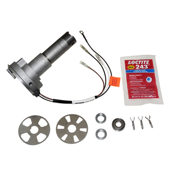
Mercury Outboard Trigger #134-3736
Trigger for 1967-79 Mercury Outboard 4-6 cylinder
OE#: 393-3736, 332-4177A 3,393-3736A 3, 393-3736A23, 393-3736A77, 393-3736A79
CDI P/N: 134-3736
This unit replaces P/N’s: 332-4177A 3,393-3736A 3,393-3736A23, 393-3736A77, and 393-3736A79
NOTICE:
THIS TRIGGER REQUIRES THE Steel DISK INCLUDED WITH IT. IT WILL NOT WORK WITH THE FACTORY DISK!!Warning! This product is designed for installation by a professional marine mechanic.
CDI cannot be held liable for injury or damage resulting from improper installation, abuse, neglect or misuse of this product. Refer to the Service Manual to set ignition timing.
DO NOT USE A MAINTAINENCE FREE OR Low MAINTAINENCE BATTERY WITH THIS SYSTEM. BATTERY Voltage IN
EXCESS OF 16 VOLTS MAY DAMAGE IGNITION PARTS (NOT COVERED UNDER WARRANTY).
INSTALLATION
1. Remove the electrical harness and the battery leads from the engine.
2. Disconnect the brown, white and black trigger wires (from the distributor body to the switch box).
3. Remove the distributor housing assembly from the engine according to the service manual.
4. Remove the distributor cap retainer clamp and screw and then lift the distributor cap from the distributor body. Take care not to damage the carbon brush inside the distributor cap. If the rotor is damaged and requires replacement, the rotor and shaft must be replaced together. THE ROTOR IS MADE ONTO THE SHAFT AND CANNOT BE REPLACED EXCEPT AS AN ASSEMBLY.
5. Remove the distributor vent tube or spark arresting vent.
6. Bend the tabs of the cap nut washer open. Unscrew the cap nut from the distributor housing. Remove the tabbed washer and wave spring. Work the tension spring off of the pin as you slide the distributor housing from the mounting adapter. Do not lose the large washer or the smaller washer inside the adapter housing.
7. CAREFULLY remove the upper bearing from the housing by working through the two holes in the sides of the housing.
Remove the ľ" nut from the shaft while holding the rotor. Use extreme care not to break the rotor tip or twist the rotor on the shaft. If this happens, the rotor and shaft assembly will have to be replaced.
8. Using a plastic mallet, GENTLY tap the rotor shaft free.
9. Discard the old trigger disk, saving the old disk spacer (between the disk and bearing). YOU must USE THE NEW Steel
DISK!
10. Inspect the distributor cap and carbon brush for damage and wear. Replace if needed.
11. Using a punch, knock out the tension spring pin. Remove the tension spring and throttle stop plate.
12. Install the tension spring pin (using a good thread-locker in the distributor housing), tension spring and throttle stop plate. Remember the spring must be free to rotate on the pin.
13. Support the new distributor housing between two blocks of wood in a vise.
14. Remove the two mounting screws from the new distributor housing cap and set the cap aside.
15. Install the old disk spacer, new trigger disk and rotor shaft into the distributor housing. Align the tang in the disk with the notch in the rotor shaft. Make sure the side marked "ROTOR SIDE" is facing the rotor. Service Note: On a double notched shaft, the wide notch is for a 4 cylinder disk and the narrow notch is for the 6 cylinder engines.
16. Using a plastic mallet, VERY CAREFULLY tap the rotor shaft into the housing. Continue work the rotor shaft into the housing
until the collar on the shaft seats into the recess in the distributor (the disk should not be loose).
17. Slide the tube spacer onto the shaft and secure with the ľ" nut. BE VERY CAREFULL WHEN TIGHTENING THE NUT OR
THE ROTOR MAY BE DAMAGED.
18. Remove the distributor from the vise and gently tap the rotor shaft on the pulley end in order to seat the lower bearing against the snap ring. Turn the housing over and check the clearance between the disk and the new distributor housing. If the disk is touching the new distributor base, you will need to dissemble the distributor housing and replace the old disk spacer with a new one (994-3538-10 spacer is 0.010 inches taller than the original).
19. Replace the new distributor housing cap using the two screws removed earlier.
20. Slide the upper bearing onto the rotor shaft and work it down until it contacts the ľ" nut.
21. Slide the large washer onto the new distributor housing and as you slide the adapter housing onto the new distributor housing, connect the tension spring to the adapter housing pin.
22. Install the small ring washer, wave spring and cap washer. Thread the cap nut on and bend the tabs of the adapter cap washer to lock the adapter cap in place.
23. Install the distributor vent tube or spark arresting vent.
24. Place the distributor cap assembly onto the distributor housing. BE CAREFULL not to bend the carbon brush sparing or damage the carbon brush. Position and install the distributor clamp and retainer with the bolt and nut.
25. Position the distributor and distributor adaptor assembly onto the powerhead mounting flange. Check to be sure the driven pulley spacer and key are in place.
26. Install the three screws securing the distributor to the powerheAdBlock.
27. Align the arrow on the pulley with the timing mark on the flywheel and install the timing belt, timing belt cover and screw (tighten to 60 inch pounds).
28. Install the ground strap and connect the Black ground wire to the engine block. Connect the Black, Brown and White wires to the switch box, matching wire colors to the terminals. If the switchbox has stud terminals, push in the ring adapter terminals
into the female bullet connectors to convert the wire connections to a ring type.